UT GeoFluids Consortium
- About Us
- Accomplishments
- Workflows
- GeoFluids 2020
- Initial (2009) Proposal
- Memorandum of Agreement (MOA)
UT GeoFluids is managed by University of Texas (Institute for Geophysics) and is currently supported by 10 energy companies. The current 10-year effort ends in 2019 and a new 10-year phase begins in 2020 (GeoFluids 2020). Our results are used to predict pressure and stress, design stable and safe drilling programs, and predict hydrocarbon migration and entrapment. We study the state and evolution of pressure, stress, deformation and fluid flow through experiments, models, and field studies:
1. Experimental: We analyze fabric, acoustic, electrical, and material properties of mudrocks : 0.1‐100 MPa. Our goal is to understand sediment response under high stress levels and complex geologic loading.
2. Poromechanical Modeling: We couple sedimentation, porous fluid flow, geologic and tectonic loading to predict pore pressure and the full stress tensor.
3. Field Studies: We analyze pore pressure, stress, and deformation in thrust belts, salt systems. We analyze case studies of challenging drilling conditions.
We produce innovative concepts and analysis work flows that couple geologic loading and fluid flow to predict pore pressure and stress in the subsurface: A) We have developed on‐line software tools that 1) predict reservoir pressure, 2) incorporate the full stress tensor to predict pore pressure. B) We have released databases and material models that describe mudrock material behavior. C) We have developed workflows that couple velocities with geomechanical modeling to predict pore pressure and stress in complex geologic settings.Peter Flemings
Co-Director of the GeoFluids Consortium (UT Austin)
pflemings@jsg.utexas.edu
512-475-8738Jack Germaine
Co-Director of the GeoFluids Consortium (Tufts)
john.germaine@tufts.edu
512-475-9520Maria Nikolinakou
Lead Scientist, GeoFluids Consortium (UT Austin)
mariakat@mail.utexas.edu
512-475-9548Carla Thomas
Project Manager, GeoFluids Consortium (UT Austin)
calra.thomas@utexas.edu
512-475-6613
Accomplishments
Experimental:
UT GeoFluids has pioneered the application of resedimentation to the systematic study of mudrock material behavior at high stress levels (up to 100 MPa (14 KSI)). We have shown that the lateral stress ratio, friction coefficient, strength, and compression behavior are stress dependent and that this behavior varies systematically with liquid limit (an easily measured parameter). We have developed models to describe smectite‐rich (Gulf of Mexico) and illite‐rich mudrocks and we have developed generalized models based on liquid limit. We have embarked on a systematic program to measure velocity (Vp & Vs) at a range of stresses and we are integrating these measurements with observations of mechanical properties. Based on our experimental results, we have developed simple spreadsheets that provide material properties as a function of depth (e.g., permeability, lateral stress ratio, friction angle, velocities – Fig. 1). These spreadsheets are freely available to UT GeoFluids members.
Fig. 1: Our experimental results are available to UT GeoFluids Members as simple spreadsheets that summarize the behavior of mudrocks and provide material properties as a function of depth. They can be used to predict fracture gradient and strength.
Geomechanical Modeling:
UT GeoFluids is a leader in the development of forward evolutionary geomechanical models that couple porous fluid flow with deposition and complex geologic loading. We have advanced our fundamental understanding on how salt advance perturbs pressure and stress in nearby sediments, and, in return, how overpressure affects the evolution of a salt system (Fig. 2). We have studied how pressure and stress evolve in fold and thrust belt systems, both in the wedge and footwall sediments. We have demonstrated that both mean and shear stress contribute to porosity and pressure changes. We have identified zones within these systems where drilling risk is high.
We have invented a method to couple seismic velocity with geomechanical modeling to predict pressure and the full stress tensor in complex geologic settings. Our approach incorporates the impact of mean and shear stress on pore pressure and stress. We and several of our industry partners are now applying this approach. We have built software to illustrate the impact of mean and shear stress on pore pressure predictions.
Fig. 2: Coupled evoluationary geomechanical models represent the frontier of basin models. They solve for the full stress tensor, incorporate complex material behavior, and simulate fluid flow and associated overpressure. They are a fundamental advance over uniaxial models (e.g. Temis or Petromod).
Field Studies:
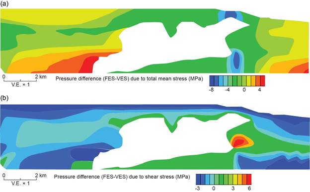
Our advances are rooted in systematic field studies. We have analyzed pressure and stress in the Mad Dog Field and demonstrated the importance of incorporating mean and shear stress into pressure prediction. We have studied pore pressure at Macondo and showed how lateral flow along the sandstone resulted in the pressure regression at the well location. We have coupled measured velocities with geomechanical modeling at Mad Dog to improve pressure and stress prediction across the field (Fig. 3). We have explored pressure, stress, and porosity evolution in fold and thrust belts.
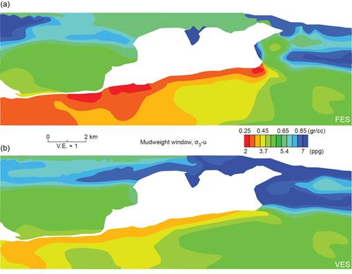
Figure 3: We enhance pressure and stress prediction by coupling velocities with geomechanical modeling. Prediction using the full stress tensor (FES; (a) in figure) yields a narrower drilling window than the vertical effective stress method (VES; (b) in figure).
Workflows
UT Centroid: We have developed an approach to predict reservoir pressure as a function of reservoir geometry and mudstone permeability (Fig. 3). This workflow is encapsulated in an online software that is freely available to UTGeoFluids members and several member companies are negotiating formal access to the approach.
Fig. 1: 'UT Centroid' provides a simple approach to predict reservoir pressure from reservoir geometry and mudstone permeability. http://geofluids.ig.utexas.edu/software/centroid/index.htm
Seismic Pressure Prediction Integrated with Geomechanical Modeling:
We have invented a workflow that integrates seismic velocity data with geomechanical modeling to predict pressure and the full stress tensor (Fig. 2) (Heidari et al). Our method incoporates the role of mean and shear stress in pressure and stress prediction and take into account complex stress states found in basins. The method represents a fundamental advance from vertical effective stress (VES) models and can be systematically incorporated into pore pressure and stress workflows.
Fig. 2: UT GeoFluids has developed a workflow to couple geomechanical modeling with seismic velocity to predict pore pressure and the full stress tensor in complex geologic settings (e.g., around salt bodies).
UT-FAST-P3
UT-FAST-P3 allows users to predict and compare pore pressure using the full stress tensor. It is an educational tool that illuminates why it is important to go beyond vertical effective stress (VES) models. Users input a measured velocity and overburden, a velocity-effective stress calibration and a frictional strength. The output is pore pressure from 3 methods: 1) vertical effective stress (VES), 2) mean effective stress (MES), and 3) the full stress tensor (FES). UT-FAST-P3 demonstrates the relative contribution of mean and deviatoric (shear) stress to pore pressure (Fig. 3); it is available to all consortium members through this link.
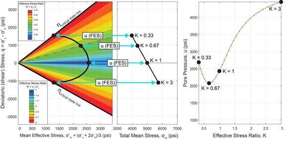
Fig. 3: UT-FAST-P3 online software incorporates both mean and shear stress into pressure prediction..
GeoFluids 2020
Three GeoFluids 2020 documents about the proposed research direction for the next 10 years of GeoFluids are available to download:
- GeoFluids 2020 Research Plan download (as shown below)
- GeoFluids 2020 full presentation download (as presented on June 5, 2018 meeting hosted by Shell)
------------------------------------------------------------------------------------------------------------------------------------------------------------------------------------------------------------
UT GeoFluids 2020 Research Plan
Peter B. Flemings1, John T. Germaine2, Maria A. Nikolinakou3
1 Executive summary
The UT GeoFluids 2020 Industrial Associates Program will study the state and evolution of pressure, stress, deformation and fluid flow through experiments, theoretical analysis, and field study. The Institute for Geophysics (UTIG) at the Jackson School of Geosciences will partner with the Dept. of Civil and Environmental Engineering at Tufts University. The cost will be $50,000 and will increment at 2%/yr. The first payment will be due in May 2019. Our research will focus on the following.
- Develop and deliver pore pressure and fracture gradient workflows.
- Link poromechanics with pressure prediction and express in whole earth stress models.
- Include stress dependency and material anisotropy in poromechanical models.
- Develop synthetic seismic models of poromechanical models.
- Study material behavior under complex stress paths representative of geologic conditions.
- Examine the role of creep in mudstones at geological stresses.
- Compare material behavior of resedimented mudstone with intact material.
- Perform field studies and build geomechanical models to predict pressure during unloading in unconventional basins
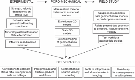
We aim to develop a unified approach that incorporates stress dependency, creep, mineralogical transformation, and loading path to illuminate the state and evolution of pressure and stress in basins. We already see evidence that this unified approach can improve well design and provide insight into a range of geological processes. These approaches will result in two and three-dimensional whole earth models that improve well design, real-time drilling, borehole stability, and reservoir simulation.
Figure 1. Interdependence of experimental, poromechanical, and field study variables.2 UT GeoFluids Plan
We produce innovative concepts that couple geology, mudrock rheology, and fluid flow to predict pressure and stress in the subsurface. Applications include pore pressure and stress prediction, the design of stable and safe drilling programs, and the study of hydrocarbon migration and entrapment. We study the state and evolution of pressure, stress, deformation and fluid migration through experiments, models, and field study:
- Experimental: We analyze fabric, acoustic, electrical, hydraulic, and material properties of mudrocks: 0.1-100 MPa.
- Poromechanical Modeling: We couple sedimentation, porous fluid flow, geologic and tectonic loading to predict pore pressure and the full stress tensor.
- Field Study: We analyze pore pressure, stress, and deformation in conventional and unconventional basins.
2.1 Experimental
2.1.1 Overview
We will characterize and quantify stress level dependence, anisotropy, and time dependence. Our goal is to better interpret field observations, calibrate numerical simulations, and provide a database to develop new models of mudrock behavior. During the past decade, we focused primarily on the stress dependent aspects of behavior during uniaxial and triaxial loading conditions and under constant loading rates. This has included various subthemes (temperature, salinity, type of mudrock, mineral transformation, etc.) but the central focus has been stress level. The next phase of the research will expand to compare intact to resedimentated behavior, the effects of loading direction, and the effects of creep.
2.1.2 Validate/calibrate resedimented behavior against intact behavior
Challenge: We have spent a decade developing material models for mudstones of different lithologies based on the resedimentation process. We will reconcile these systematic measurements against intact core samples. Does resedimented material behave similarly to intact material; if not, is there a systematic mapping that we can use to transfer insights from resedimented to intact mudrock behavior?
Research Plan:We will work with industry sponsors to acquire intact core samples of unlithified mudrocks and associated material. We will compare the material behavior of intact vs. resedimented material. We will perform laboratory experiments (uniaxial compression, undrained triaxial shear, velocity, etc.) on the intact core and the companion resedimented specimens and we will perform our typical suit of physical property tests.
We will systematically compare the resedimented behavior with the intact behavior (Figure 2 ), and with our resedimentation database. We will produce an approach, if possible, to integrate the intact and resedimentation database to develop generalized intact behavior. The results will allow our experimental work to more effectively be applied to subsurface problems.
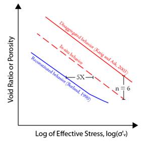
Figure 2 . The relationship between material properties of intact core and resedimented material is unclear. Karig and Ask (2003) suggest that at given effective stress, an intact mudrock is more compacted than a synthetic specimen of identical composition. In contrast, Burland (1990) suggests that the in-situ mudrock is less compacted than the synthetic material. We will compare measurements (e.g. stress-strain behavior under shear, undrained strength, friction angle, velocities, etc.) of resedimented behavior against intact behavior.2.1.3 Poromechanical behavior under generalized load conditions.
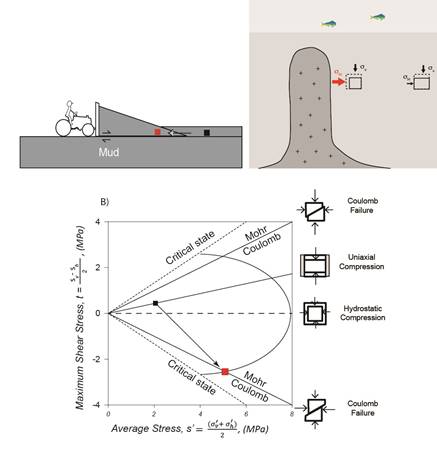
Challenge:Mudrocks in many basins undergo complex stress histories. For example, sediment deposited outside a thrust belt under uniaxial strain (K0) conditions is ultimately exposed to a large lateral stress as it is consumed into the thrust belt (Figure 3 a). Alternately, sediment adjacent to a salt diapir may undergo extreme lateral stresses (Figure 3 b).
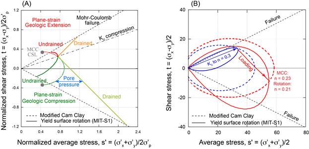
Most mathematical models for geological applications use relatively simple descriptions of material behavior. For example, we use the Modified Cam Clay model or Rockfield’s SR3 model, which are based on yield surfaces that are symmetric about the horizontal (mean stress) axis and remain as such regardless of the loading path. However, yield surfaces rotate and align with the loading axis (Figure 4 b). A critical question is what is the shape of the yield surface and how does it evolve during loading? This form of the yield surface at any given loading increment controls the amount of pore pressure generated.
.
A)
Figure 3 : Basin sediments commonly undergo complex stress histories. In either a thrust belt (a) or a salt system (b), the stress path may shift from initial deposition along the K0 trend (black square), where the horizontal stress is less than the vertical, to compressional failure (red square), where the lateral stress exceeds the vertical stress.
Research Plan:
Initially, we will investigate the shape of the yield surface at different stress levels, up to 100MPa, using our conventional triaxial apparatus (cylindrical specimens). We will also study yield surface rotation under compressional loading (horizontal major principal stress). We will next develop a 3-axis testing device capable of large normal strains in order to decouple the intermediate principal stress from the direction of loading. Such devices have been used for very low stress testing (<1 MPa) in geotechnical engineering and for rock testing at high stress, but with limited strain capability (<5%). This will be a major advancement in technology that will allow investigation of compression and shear behavior as the material transitions from a K0 state of stress to the more general stress conditions found around salt features or within thrust belts..
Figure 4 : A) Example loading paths following uniaxial compression for plane-strain conditions, predicted by Modified Cam Clay (dashed lines) and MIT-S1 (yield-surface rotation; solid lines). B) Compressional loading after uniaxial compression: iso-volumetric surface at the end of each loading predicted by MCC (symmetric with respect to x-axis) and MIT-S1 (asymmetric and rotating; Pestana et al, 2002).
2.1.4 Wave Velocity Characterization:
Challenge:Wave velocities are a function of the elastic modulus and density of the material. Most sedimentary materials are considered to be cross-anisotropic (one symmetry axis) resulting in five independent elastic parameters. Anisotropy in the sedimentary section must be corrected for us to properly image the subsurface and to estimate subsurface properties (Nihei et al., 2011). We are developing complex forward poromechanical models and we wish to understand how they would be imaged in the subsurface. To do so, we need to determine the five elastic constants and how they vary with stress state and stress level.
Research Plan:We will measure the compressional (P) and shear (S) wave velocity anisotropy as a function of stress up to 100 MPa. The measured velocities will be used to compute the elements of the stiffness matrix, which are then used to determine the velocity in any direction (e.g. Figure 5). Velocity measurements require specific technologies designed for each stress level range. We have recently developed technology up to 10 MPa which allows measurement of a) P and S waves in the axial dimension (surface mounted piezoceramic crystals in the end caps); b) P and S waves across the specimen diameter (crystals mounted directly on the specimen under the membrane) and c) one inclined P wave (side of specimen to end cap). Our next technology increment will be developing a similar capability in the triaxial cell having a capacity of 100 MPa.
Elastic anisotropy (Young's modulus, Shear modulus, and Poisson’s ratio) varies with stress level during K0 consolidation and is also be dependent on the general stress state (non-K0 conditions and proximity to the failure envelop). We will explore these velocities during different compression paths (K0, isostatic, etc.) as well as during undrained shearing.
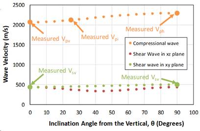
Figure 5 . Compressional and shear wave velocity as a function of angle based on measurements of five independent velocities on a specimen uniaxially consolidated to 5.8 MPa2.1.5 Visco-plastic behavior:
Challenge: Deeper, hotter, and older mudrocks are often more compacted than mudrocks at the same effective stress in the shallow section. It is also common for laboratory-measured of resedimented specimens to have a higher porosity than intact samples at the same stress level. We have ruled out the effects of pore fluid salinity, elevated temperature, and illitization. While unloading (reduction in effective stress) may account for some cases, it is unlikely to explain the ubiquitous behavior observed. We will now focus on creep as a cause for these effects.
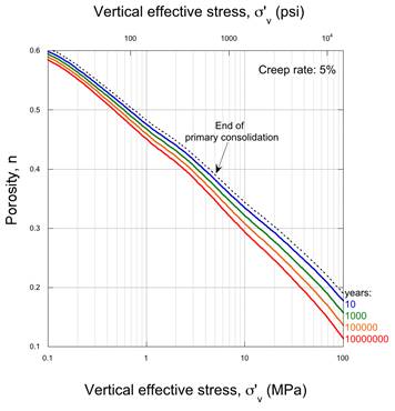
All particulate materials experience time-dependent deformations (volumetric and shear) under constant effective stress conditions. Mesri (1974) found that the rate of creep was uniquely related to the slope of the compression curve and coined this "the 4th law of soil mechanics". Relaxation is the reduction in the stress state at fixed deformation, which is a closely related time-dependent behavior to creep. Creep is often referred to as secondary compression, drained creep, and undrained creep. In the lab, creep follows primary consolidation. However, since rates of consolidation scale with the square of the drainage distance, field consolidation times are millions of times slower than the laboratory scale. It is unclear if creep occurs after primary consolidation or if it coexists with primary consolidation. This can lead to very different deformation and potentially different pore pressure predictions.
Creep under uniaxial loading has been studied extensively in the laboratory using both an incremental oedometer and constant strain rate compression testing. Creep deformations follow a linear log-time relationship. Figure 6 illustrates the potential effect of creep on compression behavior for different time scales up to 10 million years. While the numbers are approximate and based on lab measurements, Figure 6 clearly illustrates that creep may be an important factor in assessing field porosities. For example, at a 5% creep rate, a 10 m.y. old rock under a load of 100 MPa (14,500 psi) would compact 0.08 additional porosity units relative to a material recently deposited (solid red vs. dashed black lines, Figure 6).
Figure 6 . Effect of creep on compression behavior for different time scales up to 10 million years. End of primary consolidation (dashed black line) based on laboratory tests. Creep rate 5%.
Research Plan: We will perform uniaxial compression tests under varying strain rates as well as constant axial effective stress conditions (incremental loading) to characterize the creep rate and variation in the lateral stress ratio as a function of time and stress level. We will use rigid wall and triaxial devices to vary the drainage height and provide lateral stress measurements. The output of this study will be an understanding of how compression curves vary with strain rate. It will form the basis of a rate dependent mudrock model. We will also investigate how relaxation may alter the state of stress during uniaxial compression with a particular focus on how lateral stress (K0) values change as a function of relaxation.2.2 Poromechanical
2.2.1 Overview
The motivation of the poromechanical program is to study stress, pressure and deformation in complex geologic settings using field geometries and realistic material description. Our goals are to: a) estimate pore pressure and the full stress tensor under complex geologic loading; b) identify hazardous zones for drilling; c) advance our fundamental understanding of the interaction between pressure, stress, and deformation in basins; and d) develop a technical approach to address geological systems where large strains, pore fluids, and sedimentation interact. We will develop material models that describe the behavior observed in our experimental program (e.g., stress dependency, yield-surface rotation) and we will implement these models into numerical simulations. In addition, we will build 3-dimensional models of complex geologic systems and develop workflows to relate poromechanical results to velocity fields.
2.2.2 Incorporate more realistic material behavior within numerical models
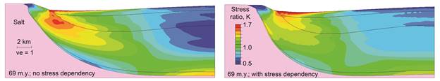
Challenge: It is necessary to include this stress and path dependence in our poromechanical models to more accurately describe earth behavior. Simple critical state soil models assume a constant frictional strength, are insensitive to the rate of loading, and do not depend on the direction of loading. Our recent experimental work has demonstrated a systematic dependence of frictional strength, undrained strength, and lateral stress ratio on stress level. For example, the predicted stresses are fundamentally different when the material properties are strength dependent (Figure 7, right) relative to when they are not (Figure 7, left). We also observe a dependence of the yield surface and iso-volumetric surfaces on stress level and loading direction.
Research plan: We will develop an enhanced critical state model that will incorporate 1) the asymmetry (rotation) and evolution of the yield surface under complex geologic loading and high stress levels, 2) stress-level dependency of frictional angle, undrained strength, and stress ratio, 3) strain rate sensitivity. We will couple this new formulation with evolutionary numerical models..
Figure 7 . Preliminary study of the effect of stress dependency on a salt system. Decrease in the frictional strength with confining stress leads to a more uniform stress state near salt.
2.2.3 3-D models of complex salt systems
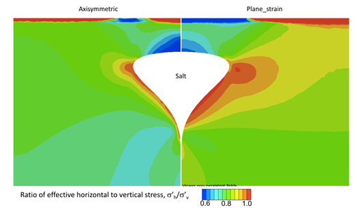
Challenge: We will extend model results to three dimensions to explore under what conditions it is appropriate to extrapolate 2D results to 3D systems (Figure 8 ). A plane strain model can over predict stresses relative to an axisymmetric model (Figure 9). Thus, while plane-strain and axisymmetric models may predict qualitatively similar behavior, the plane-strain approach predicts much higher values, because no deformation is allowed in the out-of-plane direction. At the same time, the axisymmetric model may under-predict stresses, because it cannot account for constrains in the circumferential (hoop) direction. Hence, neither approach fully represents the three-dimensional geometry of salt systems.
Research plan: We will develop 3-dimensional models and study the effect of complex geometries to stress and pressure near salt. We will compare our results with plane-strain or axisymmetric models and provide criteria and guidelines for investing in a 3-dimentional study. We will work with industry to obtain real salt geometries, predict pressure and stress and compare with field data.
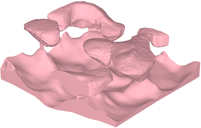
Figure 8 . Salt system offshore West Africa, (courtesy of Repsol) illustrating the complexity of the 3D salt geometry.
Figure 9 . Axisymmetric vs. plane strain salt model. Both models predict qualitatively similar behavior, however the plane-strain model predicts much higher stress values.
.
2.2.4 Synthetic Seismic of Poromechanical Models
Challenge: Our poromechanical models provide the full effective and total stress tensors, porosity and pore pressure predictions. We will develop seismic models of our poromechanical models to understand how pressure and stress are recorded in seismic data. The results may improve seismic imaging and ultimately allow inversion of pressure and stress from seismic data.
Research plan: We will couple poromechanical modeling, laboratory measurements, and seismic anisotropic-model building to develop the next generation of seismic analysis tools.
We will generate synthetic seismic data and images based on computed stresses (Figure 10A) and material properties from our poromechanical models. We will build anisotropic velocity models (Figure 10B) using published, and lab-measured, empirical and theoretical relations. We will use anisotropic models to create synthetic seismic shot gathers (Figure 10C) using the derived stiffnesses. A necessary intermediate step is the derivation of a rock-physics model to translate stresses to seismic velocities or elastic stiffnesses. Because the stress model is transversely isotropic (TI), the more convenient quantities to work in are the elastic stiffnesses. Initially, we will calculate directional-dependent velocities from the stiffnesses. Each cell in the TI model requires five independent stiffnesses. In this example (Figure 10 ), the rock-physics used relates the effective stresses to the velocities. To derive this model, first, the well-log velocities are considered relative to the maximum principal stress along the deviated wellbore. The well deviation angle and the maximum principal stress angle dictate which anisotropic, angle-dependent velocity is measured along the wellbore. Once this is done, the range of fast and slow P-wave velocities expected throughout the model are known. The empirically derived rock-physics model relates the effective-stress components to elastic stiffnesses. It then transforms the poromechanical stresses to TI elastic stiffnesses at all locations (Figure 10B). The maximum principal stress direction determines the orientation of the fast and slow velocities.
For application to field data, we will use our effective stiffnesses for imaging using TTI reverse time migration. Resulting image gathers will be flat, which can be used for subsequent AVO analysis. Note that we estimate NMO velocity and h from anisotropic velocity analysis. These will be used together with velocity data (e.g., Figure 10) for quantitative interpretation (AVO analysis) and depth imaging of field gathers. Furthermore, we will develop inversion methods for directly estimating parameters other than NMO velocity and h, directly from field seismic data.
We envision coupling modeling, lab measurements, and seismic anisotropic-model building to develop the next generation of seismic analysis tools.
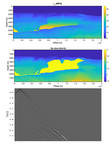
Figure 10 . A) Stress field (in-plane horizontal stress) obtained from geomechanical model; B) slow quasi-P wave velocity obtained from (A); C) A synthetic seismic shot gather computed by finite differences using (B). All shot gathers will be processed and studied for AVO and anisotropic velocity analysis..
2.2.5 Geomechanical response to unloading
Challenge: In unconventional basins, secondary pressure mechanisms (e.g. hydrocarbon generation) and/or erosion often unload the system (the present effective stress is less than the maximum effective stress in the past). Traditional effective stress approaches to pressure prediction do not hold in these environments (e.g. Couzens-Schultz et al. 2013). The challenge is to develop a quantitative physics-based understanding of how unloading impacts the stress field and pore pressure prediction.
Research plan: We will develop geomechanical models to describe pore pressure and stress response to unloading. We will specifically include the effect of the full stress tensor on pore-pressure and porosity changes during unloading. In addition, we will consider the effect of a hydrocarbon source term and the presence of multiple phases in the pore space. We will begin with the development of simple, one dimensional models and will evolve to considering two dimensional models. We will integrate our geomechanical understanding with field observations to develop a process understanding of the evolution of pressure in unconventional basins.
.
2.3 Field studies
2.3.1 Overview
We will continue to perform field studies in the Gulf of Mexico and elsewhere. In particular, we will expand our studies to include analysis of unconventional basins. Analysis of field data tests the effectiveness, approaches, and insights that we develop through our experimental and modeling work. It also trains the next generation of quantitative geoscientists.
2.3.2 Validation of poromechanical predictions with field measurements
Challenge: We have developed evolutionary poromechanical models that couple sedimentation with porous fluid flow and salt flow. We have also developed transient evolutionary models of fold-and-thrust belts. These models provide specific predictions regarding the state of stress, pressure, and deformation in complex systems. We will deliberate target data sets to test these predictions with field measurements.
Research plan: We will work with our industry members to obtain stress and pressure measurements in salt systems and in thrust belts. We will mine MDT and leak-off measurements from public databases. We will augment our estimate of stress state and pressure from borehole image logs. We will compare these field studies with poromechanical model predictions. This research will be instrumental in creating a road map that links porosity, overpressure, stress ratio, and mudrock strength with geometric features of salt systems.
2.3.3 Validation of pressure prediction workflows
Challenge: We have developed pressure prediction workflows that couple poromechanical modeling with seismic velocities. We have applied the workflow in a 2D transect in the Gulf of Mexico with limited well data. We will validate and test these approaches with analysis of field measurements in areas we apply these workflows.
Research plan: We will work with industry sponsors and service companies to release seismic data and pressure and stress data over specific fields with geometries that reflect our poromechanical model simulations. We will take advantage of newly released 3D seismic data available across the Gulf of Mexico. We will build static poromechanical models from present-day geometry and couple them with velocity data. We will validate our workflow by comparing pressure and stress predictions with available well measurements. We will use 2D and 3D poromechanical models and predict pressure across transects and across a three-dimensional area of interest. We will evaluate the relative benefits of investing into three-dimensional workflows.
2.3.5 Pressure prediction in unconventional basins
Challenge: Pore pressures are impacted by erosional unloading and hydrocarbon maturation inmany unconventional basins. As a result, effective-stress–pore-pressure prediction techniques used in conventional basins may not be successful (Couzens et al., 2013). The challenge is to develop a process understanding of how pore pressure evolves in unconventional basins and then apply this understanding to predict pressure in new locations.
Research plan: We will work with industry sponsors and service companies to obtain log and pressure data over several unconventional basins. We are considering the Powder River Basin of Wyoming and the Permian Basin of West Texas and two companies are eager to provide data to support this effort. We will first build a pore pressure database from kicks, connection gases, DFITs and production data (Ewens et al., 2012; Jones et al., 2014; Kozlowski et al., 2018). We will then study the petrophysical response of velocity (shear and density) and resistivity logs. We will integrate geologic information to understand the history of deposition and erosion, the organic content, and the timing of maturation. We will then link our observations of pressure to predictions from geomechanical models and develop a process understanding of the evolution of pressure in unconventional basins.
We wish to address the following. Can we develop a systematic approach for predicting pressure in unconventional basins and how different is this approach from workflows used in conventional basins? Does overpressure generation followed by subsequent exhumation, therefore a reduction in confining stress and cooling, enhance or reduce overpressure? What can logs tell us about the state of stress and pressure in a basin, given a known amount of erosion?2.4 Deliverables
Cuttings Protocol: We will deliver a protocol for on-site (on-rig) cleaning and testing of cuttings. We will provide correlations between liquid limits/clay fraction and stress ratio, friction angle, and undrained strength. This tool will allow quick estimation of least principal stress and strength during drilling.
Salt Pressure-Stress Atlas: We will build an atlas that relates salt geometry to pressure and stress predictions. This atlas will provide insights into qualitatively estimating stress, pressure, and hazardous zones near salt.
Road Map for Intact vs. Resedimented Behavior: We will build a database that compares intact with resedimented behavior.
Online Experimental Database: We will provide an online database containing our experimental measurements for use by the sponsors for internal evaluations.
Poromechanical Model Results: We will communicate and distribute poromechanical model results in standard industry software format and in excel spreadsheets, so that the insights are more easily applied.
Online Software: We will continue to build online software to communicate the concepts we are developing.
Workflows: We will continue to develop our workflow to couple seismic models with poromechanical models to predict pressure and stress.
Synthetic Seismic Images: We will deliver tools and workflows to generate synthetic seismic datasets from our poromechanical models.
3 Logistics
The first payment will in May of 2019. The initial annual fee will be $50,000 and this will increment at 2%/yr. There will be no penalty for withdrawing from the consortium. Members who choose to join after the first year will be required to pay the previous year’s consortium cost.
3.1.1 Current industrial associates
Industrial Associates which are currently members of the GeoFluids consortium, under the Industrial Associate Agreement will need to sign an Amendment.
3.1.2 Prospective industrial associates
Industrial Associates interested in joining the GeoFluids consortium will need to sign a new Agreement that reflects the original Agreement and the Amendment.
References
Burland JB (1990). On the compressibility and shear strength of natural clays. Geotechnique 40:329-378, doi:10.1680/geot.1990.40.3.329.
Couzens-Schultz, B. A., et al. (2013). Pore Pressure Prediction in Unconventional Resources. International Petroleum Technology Conference. Beijing, China, International Petroleum Technology Conference: 11.
Ewens, S. D., Idorenyin, E. H., apos, Donnell, P., Brunner, F., and Santo, M., 2012, Executing Minifrac Tests and Interpreting After-Closure Data for Determining Reservoir Characteristics in Unconventional Reservoirs, SPE Canadian Unconventional Resources Conference: Calgary, Alberta, Canada, Society of Petroleum Engineers, p. 14.
Jones, R. S., Jr., Pownall, B., and Franke, J., 2014, Estimating Reservoir Pressure From Early Flowback Data, Unconventional Resources Technology Conference: Denver, Colorado, USA, Unconventional Resources Technology Conference, p. 16.
Karig DE, Ask MVS (2003). Geological perspectives on consolidation of clay-rich marine sediments. Journal of Geophysical Research 108:2197, doi:2110.1029/2001JB000652.
Kozlowski, K., Da Silva, M., Brown, D., Taylor, J., Willems, H., Watson, T., Burch, D., Hutton, T., Christensen, C., and Manohar, M., 2018, The Importance of Overburden and Pore Pressure on Horizontal Stress Magnitude Determination; an Example From the Delaware Basin, SPE/AAPG/SEG Unconventional Resources Technology Conference: Houston, Texas, USA, Unconventional Resources Technology Conference, p. 15.
Mesri G, Rokhsar A (1974). Theory of consolidation for clays. Journal of the Geotechnical Engineering Division, Proceedings of the American Society of Civil Engineers 100:889-904.
Nihei K, Nakagawa, S., Reverdy, F., Myer, L., Duranti, L. (2011). Phased array compaction cell for measurement of the transversely isotropic elastic properties of compacting sediments. Geophysics 76:WA113-WA123.
Pestana JM, Whittle AJ, Gens A (2002). Evaluation of a constitutive model for clays and sands: Part II Clay behavior. International Journal for Numerical and Analytical Methods in Geomechanics 26:1123-1146.
.
Initial (2009) Proposal
download this document in PDF form
University of Texas GeoFluids Consortium (UT GeoFluids):
Mudrock Geomechanics & Pore Pressure Prediction
Description & Objectives1.0 Executive Summary
Overview: UT GeoFluids will study the state and evolution of pressure, stress, deformation and fluid migration through experiments, theoretical analysis, and field study. The Bureau of Economic Geology (BEG) at the Jackson School of Geosciences will partner with the Department of Civil and Environmental Engineering at MIT: BEG will lead the consortium.
Experimental: We will analyze the fabric, acoustic, electrical, and mechanical properties of mudrocks over effective stresses from 0.1-100 MPa. We will study 1) real geologic materials (Gulf of Mexico mudrock, Boston Blue Clay) using resedimentation techniques and 2) core from a range of depths in the subsurface. Analysis of resedimented material allows us to examine material properties of a consistent material at a range of in-situ stresses. Uniaxial consolidation experiments will measure vertical and lateral stress, resistivity, permeability, and velocity (Vp & Vs) during compression. Triaxial experiments will measure strength parameters. We will describe and quantify mudrock fabric at various effective stresses with mercury porosimetry, and x-ray goniometry and image mudrock fabric using electron beam techniques. We will 1) illuminate the origin and evolution anisotropy in mudrocks, 2) document how composition (e.g. clay/silt fraction and clay composition) controls geomechanical properties, and 3) develop a geomechanical model for mudrocks that will better allow us to predict compaction behavior, pore pressure, and borehole stability at geologic stresses.
Poro-Mechanical Modeling: We will develop and apply models that link realistic rheologies, deformation, stress (shear and normal), and pore pressure. Pressure prediction techniques and basin modeling generally assume uniaxial deformation. In areas of central interest to the petroleum industry, deformation is not uniaxial and stress and pressure are coupled in more complex ways. In thrust belts, the lateral stress is greater than the vertical stress and sediment that was originally buried in a basin under uniaxial strain is later deformed in plane strain. In the sub-salt regime, the interaction of isostatically stressed salt with sediment that bears differential stresses results in complex stress and deformation near the salt-sediment interface. To understand and ultimately predict pressures, stresses, and rock properties in these regimes, a new level of understanding, modeling, and analysis must be applied.Field Study: We will analysize pore pressure in thrust belts and in salt provinces. In the subsalt, we will analyze pressure and stress in and near the Mad Dog field to understand how pore pressure couples with salt advancement and to study the present state of stress and pressure in sub-salt systems. We will study fold thrust systems through ongoing work in the Nankai Trough. We look forward to working with industry data sets in deepwater fold-thrust belts.
Importance: Despite extensive previous work exploring mudrock compressional behavior, there are still major gaps in our understanding of mudrock evolution. We do not yet have an understanding of stress and strength behavior over a large range of effective stresses (0.1-100 MPa) and we do not fully understand the evolution of anisotropy. Our work will lay the groundwork for a new generation of basin modeling algorithms and pressure/stress prediction techniques. This new generation of modeling techniques will go beyond the restrictive assumption that deformation is uniaxial. Instead, we will couple reasonable assumptions about far field stress state with rheological models to predict stress and pressure. The results will allow us to better predict pressure, stress, borehole stability, and hydrocarbon migration in environments critical to exploration: thrust belts and sub-salt.
Reporting: The Consortium will 1) hold Annual Meetings, 2) provide Annual Reports, 3) develop an on-line database of experimental results, 4) provide Company Visits, and 5) provide Notice of Papers Submitted for Publication.
Research Team: The Consortium Team will include Peter Flemings (University of Texas at Austin), Ruarri Day-Stirrat (University of Texas at Austin), John Germaine (Massachusetts Institute of Technology), and Derek Elsworth (Pennsylvania State University). We envision supporting 10 graduate students and 3 post-doctoral scientists at 3 universities.
How Much?
Start Date: June 1, 2009
Duration: 10 years
Cost: $45,000/year
Project Director: Peter B. Flemings, Geoscientist and Professor
512-475-8738 (w)
2.0 UT GEOFLUIDS PLAN:
Pressure prediction techniques and basin models generally assume uniaxial deformation (Figure 1A). Pressure is predicted from a single effective stress-porosity relationship (Figure 1B,C) and the least principal effective stress (fracture gradient) is modeled as a fraction the vertical effective stress (parameterized by the stress ratio, Ko) (Figure 1C).
In practice, the specific nature of the porosity-effective stress relationship and the effective stress ratio (Ko) are empirically derived, have significant variation, and we do not understand well what controls this variability. At geologic stresses (0.1 -100 MPa) we do not have a clear understanding of compaction or strength behavior. We do not fully understood how the fabric of a compacting mud rock evolves. Thus, the evolution of anisotropy (strength, permeability, resistivity, velocity) is poorly undertood.
Figure 1: A) Uniaxial strain is generally assumed in pressure predictiona and basin modeling. B) Under these conditions, there is a single relationship between vertical effective stress and strain. D) In complex stress regimes, vertical and lateral strain occurs. E) Here, the rock that is subject to both vertical and lateral shortening behaves more stiffly (red dashed line) than the same rock undergoing uniaxial strain (solid black line). F) Predicted pore pressures are lower, yet horizontal stresses are higher in this example relative to the uniaxial strain example.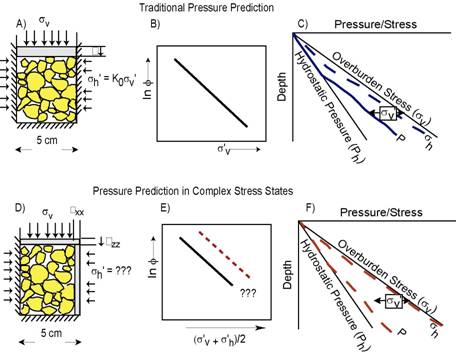
In settings of critical interest to industry, strain is not uniaxial. Under these conditions, the porosity-effective stress relationship will be different (red dashed line vs. solid black line, Fig 1E). There has been little effort to incorporate this behavior in the study of mudrock consolidation. We illustrate that rocks with the same observed porosity will have different pressures because one region was subject to uniaxial strain (top) whereas the other has both vertical and lateral strain imposed (bottom) (Figure 1).
The example above illustrates the importance of this problem for predicting pressure. However, the problem also applies to basin modeling. Most basin modeling software assumes uniaxial strain (e.g. IFP’s Temispack, IES’s Petromod, or our own (Dugan, 2000). By definition these modeling packages cannot capture the physical processes that occur when strain is not uniaxial. As a result they will incorrectly simulate pore pressures and resultant flow and they cannot capture variations in the stress field.
This consortium will pursue three directions. 1) We will perform a broad range of experimental measurements to analyze the evolution of mudrocks through mechanical compaction. 2) We will develop geological models that incorporate a full soil model and thus the effects of both mean and shear stress: we will be able to predict both stress and pressure. 3) We will pursue field studies in two environments where the uniaxial strain assumption is not appropriate: salt environments and fold-thrust environments. The goal is to develop, through analysis of data sets and theoretical modeling, a fundamental understanding of the evolution of pressure, stress, and rock properties in these systems. From this understanding we will develop specific pressure prediction and basin modeling techniques that will be broadly applicable.
2.1 Mudrock Properties: Experimental Program
Overview:
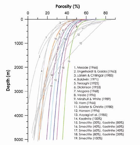
There are a wide range of porosity-effective stress relationships that have been developed (Figure 2). Burland et al. (1990) summarized the dependency of compression behavior on clay content. Karig and Hou (1992) used mixtures of material to illustrated striking differences in compression behavior between mudstones and sandstones. Fukue et al. (1986) explored the variation in compressibility for a range of clay-silt mixtures. Aplin and Yang (1995) used well cuttings to illustrate how compression behavior varies with clay content. Dewhurst and Aplin (1998, 1999) experimentally examined the evolution of permeability, porosity, specific surface area, and pore throat distribution within mudstones and siltstones of London Clay mudstone. Yang and Aplin (2004) presented compressibility behavior of well data emphasizing the importance of clay content on compressibility. Most recently, Mondol et al. (2007) described the compression and velocity behavior of synthetic mixtures ranging from pure smectite to pure kaolinite.
Figure 2: Illustration of the many porosity vs. depth relationships for mudrocks (Mondol et al., 2007).There are still major gaps in our understanding of the evolution of mudrocks. We do not yet have a predictive understanding of stress and strength behavior over a large range of effective stresses (0.1-100 MPa). How does anisotropy evolve in mud rock successions? Kwon et al. (Kwon et al., 2004a; Kwon et al., 2004b) demonstrate permeability anisotropy in Gulf Coast Wilcox formation samples at 4km, but the question of when and how anisotropy develops remains (Figure 3).
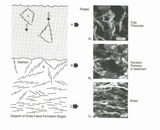
Figure 3: Shale fabric changes during consolidation. (O'Brien and Slatt, 1990).
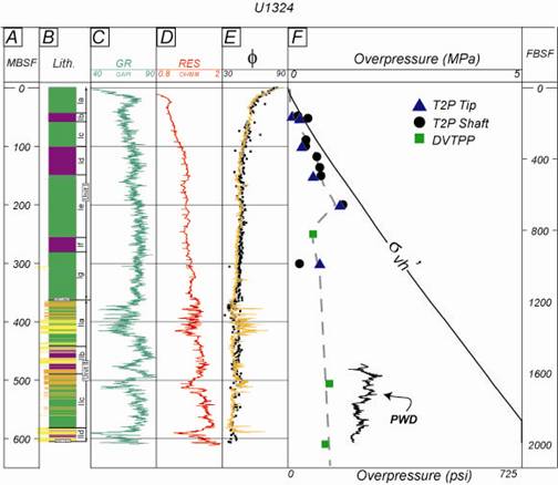
We will analyze the fabric, acoustic, electrical, and material properties of mudrocks over effective stresses from 0.1-100 MPa. We will study 1) synthetic mixtures and real geologic materials (Gulf of Mexico mudrock) using resedimentation techniques and 2) intact cores from a range of in-situ effective stresses (Ursa Region, Figure 4). We will use these materials to study the evolution of mudrocks during consolidation. We will use mercury injection porosimetry, X-ray diffraction, and Scanning Electron Microscopy and high resolution X-ray texture goniometry to characterize the evolution of pore throat geometry, quantify composition and clay fabric intensity, and provide images. We will characterize permeability, and compressibility. Analysis of resedimented material will allow us to examine material properties of a consistent material at a range of in-situ stresses. Uniaxial consolidation experiments will measure vertical and lateral stress, resistivity, permeability, and velocity (Vp & Vs) (Figure 5). Triaxial experiments will measure strength parameters. The experimental suite will be grounded and augmented by extensive whole cores from 0-600 meters below mudline in the Ursa Region of the Gulf of Mexico (Figure 5). These cores are largely composed of mudrock of a relatively homogenous composition that have been consolidated from a surface porosity of approximately 70% to a minimum porosity of 35% at a depth of 600 mbsf.
Figure 4: Hole U1324 from the Ursa Basin, Gulf of Mexico (Flemings et al., 2008). A broad range of data including intact core, logging data, and other physical property data are available.
The primary goal of the experimental program is to provide the underpinnings for more complex and comprehensive mudrock models than are currently used in the energy industry. Through this analysis we will 1) illuminate the origin and evolution of anisotropy in mudrocks, 2) illuminate how composition (e.g. clay/silt fraction and clay composition) impacts geomechanical properties, and 3) develop a geomechanical model for mudrocks that will better allow us to predict compaction behavior, pore pressure, and borehole stability at geologic stresses (Figure 5).
The long term motivation is to:
- Improve geophysical imaging by having a better understanding of propagation velocity, elastic anisotropy, and resistivity anisotropy as a function of mudrock density.
- Design drilling programs by having a better understanding of the stress profile and mechanical properties of the mudrock.
- Provide parameters for forward modeling of basin evolution
- Develop tools to predict pore pressure and stress from rock properties
We will measure the following parameters:
1. Velocity: vertical compressional (Vp) and Shear (Vs) velocity at various stress levels during uniaxial consolidation.
2. Stress (horizontal and vertical) and undrained compression strength will be measured by triaxial measurements at various stages of consolidation.
3. Resistivity: Vertical and horizontal resistivity will be measured at various stress levels during uniaxial compression.
4. Permeability: vertical permeability will be measured as a continuous function of compression. Horizontal permeability will be measured at multiple stages of the experiment.
5. Fabric: At multiple stages of the deformation, samples will be extracted from the experimental cell and analyzed for pore structure, clay alignment, etc.
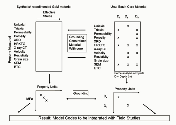
Figure 5: A full suite of experiments will be run on resedimented material (upper left). These experiments will lead to a detailed understanding of material behavior for each property over a range of stresses (lower left). In turn, measurements will be made on intact core (upper right). We will compare results from resedimented material (left side) to results from intact core (right side) and from this analysis develop a broad model of behavior of intact mudstone (lower right).
2.2 Coupled Poromechanical Modeling:
We will develop and apply coupled poromechanical models of sedimentary basin evolution. This type of modeling is used routinely in the geotechnical community. We envision two approaches; 1) we will use static stress modeling to expore the present day state of stress and pressure in meaningful geological scenarios; and 2) we will use coupled poromechanical models to describe the evolution of geological systems.
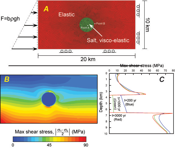
A static stress model is shown below. We have reproduced results presented by Fredrich et al (Fredrich et al., 2003) to illustrate the approach (Figure 6). We assume visco-elastic salt behavior and elastic soil behavior. The necessity for both isostatic stresses in the salt and continuity of deformations at the salt/formation interface can induce stress perturbations and stress rotations in the near-salt formations (Figure 6) (Fredrich et al., 2003; Rohleder et al., 2003). We observe signficant stress concentrations at the top and base of the salt body (Figure 6, bottom Left). Large differences in stresses can be generated that, if sufficient, induce shear failure of the formation near salt. This approach provides fascinating insight into several important issues including: 1) how to estimate vertical stress in salt systems; 2) the behavior of least principal stress at the salt-sediment interface; 3) where high shear is encountered and failure might be expected.
We will further this approach in the following ways. First we will consider realistic geometries as encountered in the case studies that we will purse (see Section 3.3). Second, we will incorporate a more realistic rock rheology into the model. We will most likely start with a Cam Clay soil model to simulate the in-situ stress state. This step is a significant one as during the relaxation process, there may be significant inelastic strains. Finally, we will couple fluid flow and stress behavior in the static stress models.
Figure 6. A: Two dimensional static stress model of circular salt body encased in elastic solid. Gravity (rgh)is included as body force. Salt is assumed to be viscoelastic (E=30GPa, v= 0.25,m= 1e19 PaS) and sediment is assumed to behave elastically (E=30GPa, v= 0.25). Boundary conditions: lateral stress increases linearly from 0 on the surface by the equation F=brgh: b is assumed to equal 0.7 to simulate a passive margin. B: maximum shear stress. Stress concentration occurs in the surrounding sediments on top and beneath the salt. C: evolution of differential shear stress along a centerline through the salt sphere during relaxation. Shear stresses in the salt gradually disappear during the processes of viscous stress relaxation.
Our second step in poromechanical modeling will be to simulate the evolution of geological systems. At the broadest level, we will incorporate stress modeling within basin modeling codes. Thus, we will go beyond current basin models (e.g. Petromod or Temis) to models that calculate stress, and deformation beyond uniaxial. We will work with the Applied Geophysics Laboratory in this development and we present one example of previous work done by AGL.
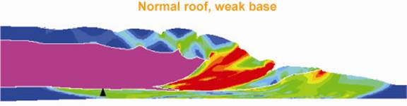
In Figure 7, a salt sheet has advanced over the underlying material. The result is concentrated zones of shear in front of the salt body. The models will require significant complexity. In particular, we envision significant problems of re-gridding around zones of large displacement.
Figure 7: Finite Element model of salt sheet advance by Dan Schultz-Ela and provided courtesy of the AGL (http://www.beg.utexas.edu/indassoc/agl/agl_if.html). Finite-element models suggest that basal shear is facilitated by very weak (overpressured) subsalt sediments. The structural style of the sheet toe may therefore be providing an indication of pressure conditions beneath the sheet. Weak sediments also permit subsalt deformation, including a footwall wedge.Memorandum of Agreement
download this document in PDF form
M E M O R A N D U M
To: From:
Institute for Geophysics
Jackson School of Geosciences
Email: (pflemings@jsg.utexas.edu)
Phone:(512-750-8411)Re: Date: .
This should be signed by a cognizant official within your organization.The signed MOA should returned to:
Ms. Sara Sieberath
Research Administration Manager
Institute for Geophysics
The University of Texas at Austin
PO Box 7456
Austin, TX 78713
sara@ig.utexas.eduThank you for your support of UT GeoFluids.
Memorandum of Agreement
Between
The University of Texas at Austin
and
______________
_____________, hereinafter referred to as "Industrial Associate," and The University of Texas at Austin, hereinafter referred to as "University," hereby agree as follows: 1. 2.
Year
Amount
Year
Amount
2009
45,000
2014
54,700
2010
46,800
2015
56,900
2011
48,700
2016
59,200
2012
50,600
2017
61,600
2013
52,600
2018
64,100
3. 4. 5. 6. 7. 8. 9. Accepted and Agreed to:
THE UNIVERSITY OF TEXAS AT AUSTIN INDUSTRIAL ASSOCIATE
Office of Sponsored Projects Date Date
Peter B. Flemings Date Date
Principal Investigator.