
Sub-bottom Profiling Systems at UTIG

UTIG owns and maintains an integrated sonar system for use in conducting Compressed High Intensity Radar Pulse (CHIRP) subbottom profiling of the upper sediment layers of the ocean bottom or various fresh water systems. The 3200-XS system was purchased in 2007 from Edgetech Corp. of West Wareham, MA (see www.edgetech.com) and can be deployed in water depths from ~2 m to >300 m with an optimum towing height of 3-5 m above seafloor. Deployment and recovery of the towfish can be done by shipboard winches for shallower deployments or a larger UTIG-owned Electro-Hydraulic winch. Constraints on vessel size are dependent on shipboard winches capability of handling either the large (190kg SB-512i) or small (76 kg SB-216S) towfish. Power control, navigation, video display, data acquisition and data storage are all performed by one topside processing unit. The system can be powered by 18-36 VDC or 110/240 VAC (auto-ranging). Contact John Goff (goff at ig.utexas.edu) for more information.
The system is presently comprised of:
- 3200-XS topside computer processor
- 4-transducer SB-512i towfish
- 1-transducer SB-216s towfish
- electro-hydraulic winch with 500 m of armored tow cable
- 3 shallow water tow cables of 10, 25, and 50 m length
- GPS navigation system (see below for details)

Topside Computer Processor:
The 3200XS topside unit (at left) consists of a ruggedized, 19” rack mount processing computer with peripheral flat panel screen, keyboard and trackball. Navigation input is via NMEA 0183 data stream through a serial port that is written into the headers and is DGPS-compatible. Data are stored in either native Edgetech (.jsf) format or industry standard SEG-Y format and can be downloaded via DVD-RW, USB port, or LAN connection. Power amplifier is 2KW. The DISCOVER software provided by Edgetech can be used for bottom sediment classification, bottom tracking, and heave compensation. Ping rates of up to 18 Hz are possible. Seismic processing and data quality control have been performed in the field using UTIG-licensed software (Focus, Paradigm Geophysical) on laptop computers. Availability of this service is determined by software licensing and personnel issues.
 SB-216S Towfish:
The user also has the option of using the lighter (76 kg) and smaller (105 cm [L] x 67 [W] x 40 [H]) towfish for shallower water and/or smaller boat operations. The smaller unit has been deployed on UTIG’s 22’ trailered boat (R/V Lake Itasca). The 216i is a single transducer towfish with a pulse frequency range of 2-16 kHz. User-selected frequencies are 2-16 kHz, 2-12 kHz, and 2-10 kHz. Typical vertical resolution limits depend on pulse range selected, but average 6-10 cm. Penetration ranges from ~6 m in coarse sands and gravels to ~80 m in acoustically transparent muds. Beam width is 17°–24°. Optimal tow speed is 3-5 kts. Maximum operating depth is 300 m. When not utilizing the electro-hydraulic winch, the fish is towed with deck cables (10, 25 and 50 m long) of 3 shielded twisted pairs (5 used). These cables only transmit and receive the pulse and their use requires an additional winch cable to take the drag weight of the fish.

SB-512i Towfish:
The 512i is a quad-transducer, 190 kg (160cm [L] x 124 [W] x 47 [H]) towfish with a frequency range of 500 Hz to 12 kHz. Pulse frequency range is user-selected among 2-12 kHz, 2-8 kHz, 1.5-7.5 kHz, 1-6 kHz, 1-5 kHz, and 0.5-5 kHz. Typical vertical resolution limits depend on pulse range selected, but average 8-20 cm. Penetration ranges from ~20 m in coarse sands and gravels to ~200 m in acoustically transparent muds. Beam width is 16°–32°. Optimal tow speed is 3-5 kts. Maximum operating depth is 300 m. When not utilizing the electro-hydraulic winch, the fish is towed with deck cables (10, 25 and 50 m long) of 3 shielded twisted pairs (5 used). These cables only transmit and receive the pulse and their use requires an additional winch cable to take the drag weight of the fish (Fig. 3).

Marine Electro-Hydraulic Winch:
The DT Marine® electro-hydraulic winch is necessary to deploy the towfish in working water depths greater than ~50 m and gives the user the option of deploying on vessels without sufficient winch capability, as long as an adequate A-frame and block are available. The winch is a 210 HP, remote control unit with IEC 8-way stainless steel slip ring with mating connector to deck cable. The unit, excluding shipping crate, is approximately 42"x46"x44" in size and has a shipping weight of 2500 lbs. The 500 m long double armored tow cable (does not require additional tow wire) is equipped with subsea and surface terminations to attach to the topside processor or either towfish.

Envelope (top) and full-waveform (bottom) CHIRP data collected within the New England Mud Patch. The more commonly-used envelope data are best used for "big picture" images of the line, whereas the full waveform data are better for detailed imaging.
CHIRP Processing at UTIG:
Chirp technology is a widespread and valuable acoustic tool for imaging the shallow seabed in great detail and resolution. Such data are used in a wide range of applications, including academic investigation of modern to Quaternary sedimentary structures and processes and more applied goals such as hazard surveys for drilling or delineating offshore sand resources. However, in our experience, there is tremendous inconsistency in how chirp data are processed prior to visualization and interpretation. Less experienced users will take a "turnkey" approach, taking the raw output from the chirp system and inputting it into interpretation software. This is doable because chirp are internally processed to a large extent: a complex, swept-frequency pulse is match-filtered internally before it is shown on-screen and output to file. This "raw" product is visually appealing and interpretable, but is far from the best possible visualization of the data, nor is it the most accurate in terms of location and depth. Visualization is greatly improved by two processing steps in particular: filtering of the seafloor arrival to remove heave artifacts, and balancing of trace amplitudes which are modulated by pitching of the towfish. Layback, towfish depth and tidal corrections are also necessary to place the data in the most accurate location and depth context. Nevertheless, even among users who do have the sophistication to apply these basic processing steps, there is often ignorance of, or lack of appreciation for, the fact that modern chirp systems output multiple, complimentary data forms (see figure). The envelope record (absolute value of the amplitudes contained in the match filtered data) is the traditional way to visualize chirp data, and is the standard product for most users. We find envelope records to be most useful for visualizing the "big picture" of the stratigraphy over a wide field of view. The value of the full-waveform records of the match filter product (positive and negative real number amplitude values), the other primary output, is less widely appreciated. We find these images to be valuable for discerning the highest-resolution and subtlest details available in the data, which are often completely missed in the envelope record. The full-waveform arrivals provide a more accurate basis for picking the seafloor and, unlike the envelope data, the full-waveform data can be used in more advanced processing steps, such as deconvolution to further sharpen the image, or migration to ameliorate parabolic reflections (an issue when the chirp data are collected at high altitude above the seabed).
Portable 3.5kHz System:
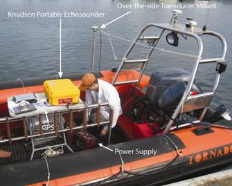
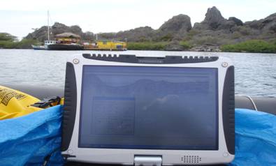
UTIG now houses a highly portable chirp (3.5 kHz center-frequency) profiling system capable of being deployed on the smallest of vessels, including skiffs, dories, or other similar craft (Fig. 1). The system consists of a portable version of the the Knudsen® 320 series echosounder and a single MASSA 3.5 kHz transducer, all of which is powered by a single 12 volt battery. The system can generate bottom and sub-bottom image from 3 – 200 m water depth in moderate-to-calm seas (i.e., swells no greater than 1 m). Data are displayed real-time using Knudsen Engineering® software. The Knudsen system generates SEG-Y files recognized by most seismic data processing packages. The system also comes with a GPS navigation unit that stamps the position at each shot point in the SEG-Y header.
Contact John Goff (goff at ig.utexas.edu) for more information.
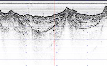
Real-time data collected at Curacao, Netherlands Antilles.
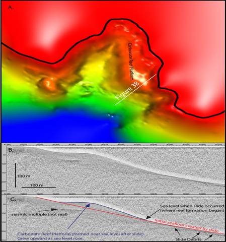
A) Map view of the seafloor for Caracas Bay in Curacao imaged by interpolating several closely spaced chirp lines. White line is the chirp profile shown in panels B and C. B) Uninterpreted chirp profile from Caracas Bay (see A for location). C) Interpreted version of same profile (see panel A for location).