
Portable High-Resolution Multichannel Seismic System
Introduction
UTIG owns and maintains elements of a self-contained, portable, high resolution multichannel seismic (MCS) system that has been used over the past several years in salt- and fresh-water depths from ~4m to over 1km, on vessels from 10m to 35m in length. The 24-channel system is designed to be transported worldwide and to be installed on vessels of opportunity. Survey design, navigation, data acquisition, and near real-time MCS processing can be performed on non-dedicated laptops in the field. Deployment and recovery of gear is done by hand, requiring as few as 3 persons. The only constraints on the system are weight limits of the vessel and electrical requirements of the dedicated air compressors. For platforms with insufficient electrical capabilities, a fuel-powered generator or air compressor can be rented as a substitute. Contact Steffen Saustrup (steffen at ig.utexas.edu) for more information.
The system is presently comprised of:
2 24-channel streamers (1 active, 1 backup)
2 Airguns (Bolt 1-20 in3, Sercel Mini GI 15/15-30/30 in3)
2 Electric Compressors (25 and 11 and scfm)
Air Receiver
Firing controller
Geode seismic recorder
GPS system
Laptop computers (navigation, acquisition, onboard QC/processing)
Disk/DVD output media
Streamer
The seismic receiver is a Beam Systems, Inc.® (Pearland, TX),100m (75 m active), 24-channel, oil-filled, analog cable (see Figures 1, 2). 72 hydrophones (Teledyne Model T-2) are grouped three to a channel, group spacing is 3.125 m. The cable is 1.6 inch in diameter, liquid filled (Isopar M fluid). Nominal tow depth is 1 m or less. The cable can is easily deployed directly from the wooden shipping reel (see Figure 2) by hand, or can be wound around any available winch drum for mechanical deployment/recovery. A second, identical streamer is kept as a spare.
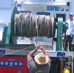
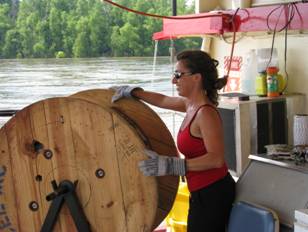
Fig. 1. Streamer deployed from winch Fig. 2. Streamer deployed from shipping reel.
drum. Sabine Bank, Western Pacific, 2006 Mississippi River, 2008
Airguns
There are two available seismic sources, a Bolt® 600 BT airgun and a Sercel Mini GI airgun.
The Bolt source can be configured with available firing chamber sizes of 1, 5, 10, or 20 in3 (see Figure 3). Firing pressure can be regulated at up to 2000 psi. Source frequency band at 20 in3 is ~70-400 Hz, with maximum power at approximately 200 Hz. The airgun is towed below a single available Norwegian-style float (see Figure 4) at a depth of 1 m or less, ~15 m behind the stern.
The mini-GI source (see Figures 5, 6) can be configured in harmonic or true GI mode, with each chamber at 15, 20, or 30 in3 (total volume of 30, 40, or 60 in3). Firing pressure is nominally 2000 psi, up to 3000 psi. Source frequency band at 15/15 in3 is ~60-400 Hz, with virtually no air bubble pulse.
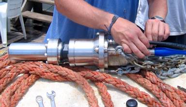
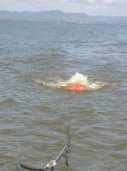
Fig. 3. Bolt 600BT sound source equipped with 20 in3 chamber. Fig. 4. Airgun towed behind a small vessel, Lake Nicaragua, 2006.
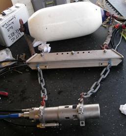
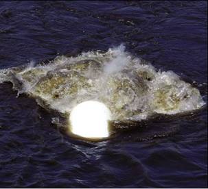
Fig. 5. Mini GI source with buoy and hanger. Fig. 6. Mini GI source firing.
Compressors
Compressed air is provided by either (or both) of two Max-Air® (Kerrville, TX) electric compressors: the Mega-Max 6000 (3-phase power, 25.2 scfm, see Figures 7, 8); and the Max-Air 90 (single-phase power, 10.8 scfm, see Figure 9). Air is stored at 5000 psi and regulated down to firing pressure (2000 psi) through a manifold and receiver system (see Figures 10,11).
Two compressor motors (50-cycle and 60-cycle) are currently available for the larger compressor depending on the power source available. This compressor is wired with a soft-start circuit, greatly reducing the power spike at start-up. Power options are:
- 50-cycle (Europe/Asia), 3-phase, 220/380/440 volts, 20 horsepower.
Power requirements are:
Volts Full-Load Amps Breaker Amps Minimum Wire Gauge
220 54 100 4
380 31 90 4
440 27 60 10
- 60-cycle (North America), 3-phase, 208/230/460 volts, 20 horsepower.
Power Requirements are:
Full-Load Working Breaker Minimum
Volts Amps Amps Amps Wire Gauge
208 62.1 32 100 4
230 54 90 4
460 27 60 10
Dimensions: 39”(W) x 36” (D) x 59” (H)
Weight: 830 lbs (377 kg)
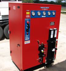
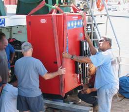
Fig. 7. Mega-Max Compressor. Fig. 8. Compressor being installed on deck, ALIS.
The more portable Max-Air 90 compressor is suitable for platforms with space or power constraints:
60-cycle, single phase, 220 volts, 7.5 HP. Power requirements are:
Volts Full-Load Amps Breaker Amps Minimum Wire Gauge
220 30 80 8
Dimensions: 40”(W) x 20” (D) x 28.5” (H)
Weight: 336 lbs (153 kg)
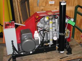
Fig. 9. Max-Air 90 compressor. Pen for scale at bottom right.
Either compressor can be located indoors or on deck, provided the deck area is well ventilated and at least partially protected from the elements. Compressor operation is automated and relatively quiet compared to gasoline- or diesel-powered compressors.
Air Receiver
Compressed air is stored at 5000 psi in a pressure-regulated, vertical 4-pack cylinder rack. Air from the receiver is regulated down to a lower pressure (normally 2000 psi) for firing the sound source.
Dimensions: 25” (W) x 25” (D) x 73” (H)
Weight: 860 lbs (391 kg)
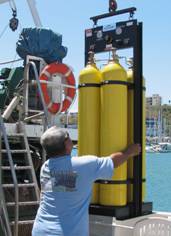
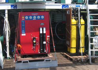
Fig. 10. Receiver being mounted Fig. 11. Compressor and receiver installed on deck,
on deck, ALIS. ALIS.
Firing Controller
The source is controlled by a Real Time Systems® (Fredericksburg, TX) HotShot firing controller (See Figure 12). This controller is capable of firing and synchronizing up to 4 Bolt airguns or 2 GI guns. Firing is triggered by an internal clock or an external signal.. The HotShot shotbox requires 110 VAC power.
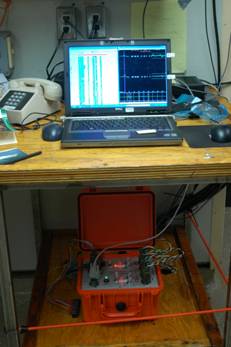
Fig 12. HotShot firing controller with
firing laptop.
Seismic Recorder
Analog signals from the cable are digitized and recorded using a Geometrics® Geode 24-channel seismic recorder, and accompanying Geometrics® SGOS software running on a laptop. The Geode requires 12-volt battery (car battery or similar). Data are stored on disk in either SEG-2 or SEG-Y format. Commonly, 1 second of data is recorded (see seismic section, Figure 13).
Laptops
All seismic recording, data storage, navigation, data processing and data archival are performed on two or three laptop computers; reliable 110v or 220v power is required. Real-time data QC and navigation display are available.
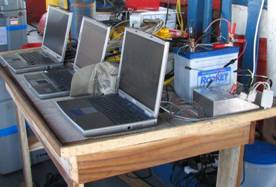
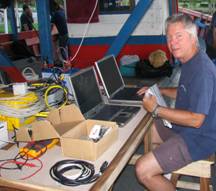
Fig. 13. Laptop/Geode/Shotbox set-up in the field: Nicaragua, 2006.
GPS
Navigation data are acquired from a portable GPS antenna or copied from the vessel’s own GPS system (NMEA), if such is available (see Figure 14). Charts and real-time navigation can be displayed on a laptop using commercial software. Navigation data are also stored on disk and written into the SEG-Y trace headers. An additional navigation display may be located on the bridge, if necessary for steering the vessel.
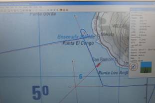
Fig. 14. Typical navigation display.
Output Media
Raw seismic data, processed seismic data, and navigation data are typically stored on external hard drives and then copied to DVD on a daily basis.
Firing Rates
Firing rates are highly variable depending on which compressor, airgun, and source volume are used. Using the Bolt airgun at full (20 in3 ) volume, a firing interval of 4s is sustainable indefinitely using the larger compressor. Firing at 2-3s intervals is possible for an hour or two at a time, allowing the compressor ~30 minutes to recharge between profiles. A sustainable firing interval of ~10s has been observed using the mini-GI airgun in the 15/15 in3 configuration. Firing smaller or larger volumes will vary the firing intervals approximately linearly; firing intervals using the smaller compressor will be approximately double these figures.
Towing
Towing strains are light enough for all deployments and recoveries to be performed by hand (see Figures 1, 15, 18). The system has been towed with as little as a 40 hp outboard motor. Typically, the source and the streamer are kept a minimum of 2 m apart laterally to protect the cable. The source and the nearest active channel are both generally located ~15 m astern of the vessel, at which distance the source is barely audible aboard the vessel. A turn radius as small as 100 m is possible with the cable deployed.
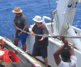
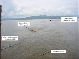
Fig. 15. Streamer deployment. Fig. 16. A typical towing arrangement.
Processing
Seismic processing and data quality control have been performed in the field using UTIG-licensed software (Focus, Paradigm Geophysical®) on laptop computers. Availability of this service is determined by software licensing and personnel issues.
Data Examples
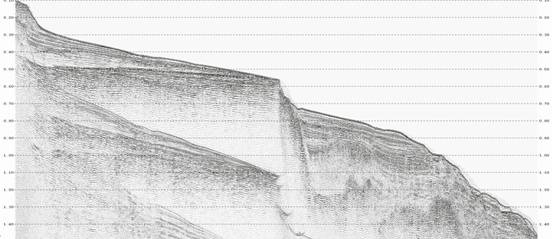
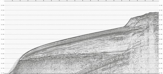
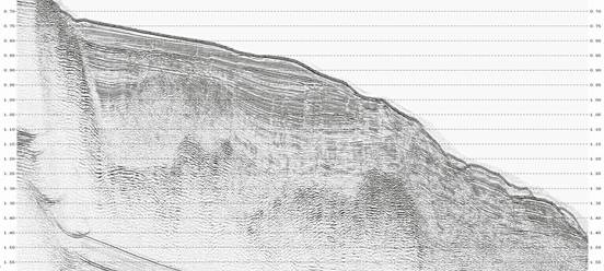
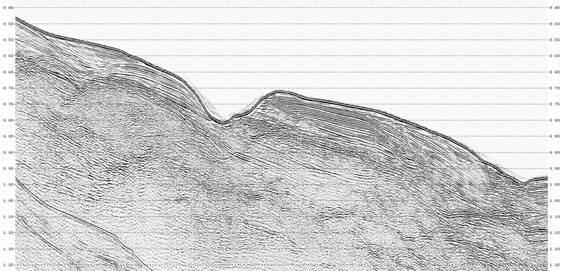
Fig. 17. Some examples of processed MCS data acquired with the UTIG system. These profiles are from the flanks of New Caledonia.
Field Gallery
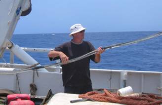
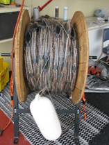
Fig. 18. Streamer deployment from ALIS, Fig. 19. Streamer and stand,
Sabine Bank, western Pacific, 2006. Mississippi River, 2008.
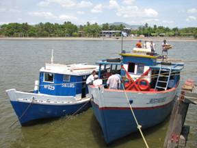
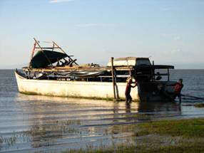
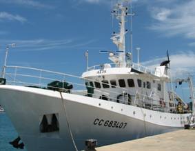
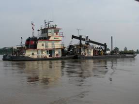
Fig. 20. Five of the vessels that have towed the UTIG system.